 Q. No.
A parallel plate condenser has a capacitance \(50~\mu\text{F}\) in air and \(110~\mu\text{F}\) when immersed in an oil. The dielectric constant \(k\) of the oil is:
1. \(0.45\)
2. \(0.55\)
3. \(1.10\)
4. \(2.20\)


Two parallel metal plates having charges +Q and –Q, face each other at a certain distance between them. If the plates are now dipped in the kerosene oil tank, the electric field between the plates will:
| 1. | increase. | 2. | decrease. |
| 3. | remain the same. | 4. | become zero. |
The capacitance of a parallel plate capacitor is C. If a dielectric slab of thickness equal to one-fourth of the plate separation and dielectric constant K is inserted between the plates, then the new capacitance will be:
| 1. | \(KC \over 2(K+1)\) | 2. | \(2KC \over K+1\) |
| 3. | \(5KC \over 4K+1\) | 4. | \(4KC \over 3K+1\) |
Two thin dielectric slabs of dielectric constants K1&K2 () are inserted between plates of a parallel capacitor, as shown in the figure. The variation of electric field E between the plates with distance d as measured from plate P is correctly shown by:

| 1. |  |
2. |  |
| 3. |  |
4. |  |
A parallel plate capacitor with cross-sectional area A and separation d has air between the plates. An insulating slab of the same area but the thickness of d/2 is inserted between the plates as shown in the figure having a dielectric constant, K=4. The ratio of new capacitance to its original capacitance will be:
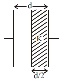
| 1. | 2: 1 | 2. | 8: 5 |
| 3. | 6: 5 | 4. | 4: 1 |
A parallel plate capacitor has capacitance \(C\). If it is equally filled with parallel layers of materials of dielectric constants \(K_1\) and \(K_2\), its capacity becomes \(C_1\). The ratio of \(C_1\) to \(C\) is:
| 1. | \(K_1 + K_2\) | 2. | \(\frac{K_{1} K_{2}}{K_{1}-K_{2}}\) |
| 3. | \(\frac{K_{1}+K_{2}}{K_{1} K_{2}}\) | 4. | \(\frac{2 K_{1} K_{2}}{K_{1}+K_{2}}\) |
The dielectric constant of pure water is 81. Its permittivity will be: (in MKS units)
1.
2.
3.
4.
The insulation property of air breaks down at V/m. The maximum charge that can be given to a sphere of diameter 5 m is approximately:
1.
2.
3.
4.
A parallel plate capacitor is made of two dielectric blocks in series. One of the blocks has thickness d1 and dielectric constant K1 and the other has thickness d2 and dielectric constant K2, as shown in the figure. This arrangement can be thought of as a dielectric slab of thickness d = d1 + d2 and effective dielectric constant K. K is:

| 1. | \(\frac{\mathrm{K}_{1} \mathrm{~d}_{1}+\mathrm{K}_{2} \mathrm{~d}_{2}}{\mathrm{~d}_{1}+\mathrm{d}_{1}}\) | 2. | \(\frac{\mathrm{K}_{1} \mathrm{~d}_{1}+\mathrm{K}_{2} \mathrm{~d}_{2}}{\mathrm{~K}_{1}+\mathrm{K}_{2}}\) |
| 3. | \(\frac{\mathrm{K}_{1} \mathrm{~K}_{2}\left(\mathrm{~d}_{1}+\mathrm{d}_{2}\right)}{\mathrm{K}_{1} \mathrm{~d}_{2}+\mathrm{K}_{2} \mathrm{~d}_{1}}\) | 4. | \(\frac{2 \mathrm{~K}_{1} \mathrm{~K}_{2}}{\mathrm{~K}_{1}+\mathrm{K}_{2}}\) |
A parallel plate condenser is filled with two dielectrics as shown. Area of each plate is A metre2 and the separation is t metre. The dielectric constants are k1 and k2 respectively. Its capacitance in farad will be:

1.
2.
3.
4.
© 2024 GoodEd Technologies Pvt. Ltd.