If each resistance in the figure is of 9 then reading of ammeter is
1. 5 A
2. 8 A
3. 2 A
4. 9 A
In the circuit shown, the point 'B' is earthed. The potential at the point 'A' is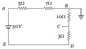
1. 14 V
2. 24 V
3. 26 V
4. 50 V
In the figure, the value of resistors to be connected between C and D so that the resistance of the entire circuit between A and B does not change with the number of elementary sets used is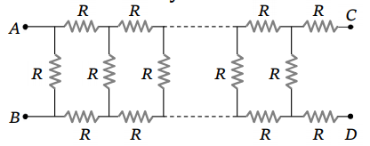
1. R
2. R
3. 3 R
4. R
Find the equivalent resistance between the points a and b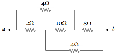
1. 2
2. 4
3. 8
4. 16
In an electrical cable, there is a single wire of radius 9 mm of copper. Its resistance is 5 . the cable is replaced by 6 different insulated copper wires, the radius of each wire is 3mm. Now the total resistance of the cable will be
1. 7.5
2. 45
3. 90
4. 270
As the switch S is closed in the circuit shown in figure, current passed through it is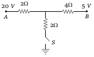
1. 4.5 A
2. 6.0 A
3. 3.0 A
4. zero
If each of the resistance of hte network shown in the figure is R, the equivalent resistance between A and B is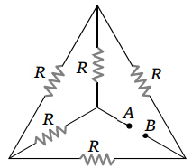
1. 5 R
2. 3 R
3. R
4. R/2
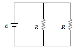
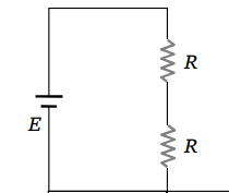
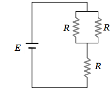
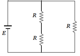
Consider four circuits shown in the figure below. In which circuit power dissipated is greatest (Neglect the internal resistance of the power supply)
1. 
2. 
3. 
4. 
The n rows each containing m cells in series are joined in parallel. The maximum current is taken fro this combination across an external resistance of 3 resistance. If the total number of cells used are 24 and internal resistance of each cell is 0.5 then
1. m = 8, n = 3
2. m = 6, n = 4
3. m = 12, n = 2
4. m = 2, n = 12
A cell of constant e.m.f first connected to a resistance R1 and then conncted to a resistance R2. If power delivered in both cases is then the internet resistance of the cell is
1.
2.
3.
4.
In the figure shown, the capacity of the condenser C is 2 F. The current is 2 resistor is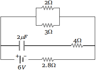
1. 9 A
2. 0.9 A
3.
4.
In the circuit shown, the value of each of the resistances is \(r\). The equivalent resistance of the circuit between terminals \(A\) and \(B\) will be:

| 1. | \(\dfrac{4r}{3}\) | 2. | \(\dfrac{3r}{2}\) |
| 3. | \(\dfrac{r}{3}\) | 4. | \(\dfrac{8r}{7}\) |
Two cells of equal e.m.f. and of internal resistances and are connected in series. On connecting this combination to an exyernal resistance R, it is observed that the potential difference across the first cell becomes zero. The value of R will be
1. \(r_1+r_2\)The effective resistance between points P and Q of the electrical circuit shown in the figure is

1. 2 Rr / (R + r)
2. 8R (R + r) / (3R + r)
3. 2r + 4 R
4. 5 R/2 + 2r
A wire of resistor R is bent into a circular ring of radius r. Equivalent resistance between two points X and Y on its circumference, when angle XOY is , can be given by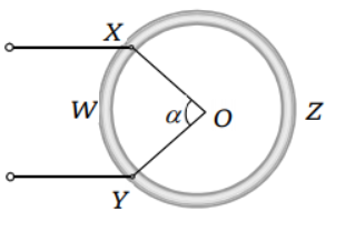
1.
2.
3.
4.
In the following circuit a 10m long potentiometer wire with resistance 1.2 ohm/m, a resistance R1 and an accumulator of emf 2V are connected in series. When the emf of thermocouple is 2.4 mV then the deflection in galvanometer is zero. The current supplied by the accumulator will be

1.
2.
3.
4.
In the following star circuit diagram (figure), the equivalent resistance between the point A and H will be

1. 1.944r
2. o.973r
3. o.486r
4. o.23r
The V-i graph for a conductor at temperature and are shown in the figure. ( - ) is proportional to
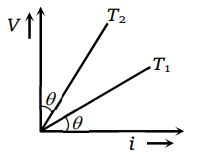
1. cos 2
2. sin
3. cot 2
4. tan
A resistance of 4 and a wire of length 5 meters and resistance 5 are joined in series and connected to cell of e.m.f. 10 V and internal resistance 1. A parallel combination of two identical cells is balanced across 300 cm of the wire. The e.m.f. E of each cell is
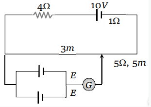
1. 1.5 V
2. 3.0 V
3. 0.67 V
4. 1.33 V